Overview
MouseTrap is a project that I did over the summer of 2007 with help from Douglas Repetto (Computer Music) and Dan Ellis (Electrical Engineering) to design an inexpensive and easy to build capacitive distance sensor that outputs 0-5V control voltage. This allows the sensor to be easily interfaced with a broad variety of devices, from analog synthesizers to microcontrollers. This project was funded by a generous grant from the Columbia University Electrical Engineering Department.
Operation
The operation of the device is relatively simple, and is divided into two stages. The first stage generates an oscillating signal whose frequency is dependent on the capacitance of the antenna. This is exactly what a Theremin does. The second stage simply uses a frequency-to-voltage converter (the LM2917) to generate a voltage from 0-5V. To get the data into my computer I’ve been using an Arduino board with Hans-Christoph Steiner’s PDuino firmware.
Construction
Because of the high-frequency oscillators in this circuit, the platform on which you build the circuit has a big impact on performance. You could build it on a breadboard, but you’ll need to change most of the capacitors to account for the extra parasitic capacitances of the board itself. You also could probably get decent performance from a perf board, but if you can get a PCB, that’s the best. Initially I made my boards on a CNC machine we have here at the Computer Music Center at Columbia, which was great for rapid prototyping, but much harder to solder than a factory-fabricated board. I can recommend Advanced Circuits’ barebones service for small PCB runs, as long as you don’t need a silkscreen layer. I bought ten boards for $6.90 each and got a coaster, t-shirt and 2 bags of popcorn with my order. Also, I intentionally made the PCB design single-layer, so it should be easy to etch chemically if that’s your thing. Some of the pads are quite small though, so I wouldn’t try it yourself unless you have a drill press.
The box I used is an FLX-2535 from PacTec. It’s available from Mouser, as are the banana jacks. I bought the power connector and binding post for the antenna connection at Radio Shack, but you could probably get those online, also. Radio Shack has a regulated 6V power supply for about 12 bucks that can deliver 300 mA of current, which is enough to run about 10 of these, so I can recommend that. Make sure you get a regulated power supply because the oscillators frequencies will vary with supply voltage, so you want to make sure it’s a constant 6V regardless of how much current you’re drawing. The power plug is Radio Shack’s “M” size, which is standard for most guitar effects pedals, which means that you can easily find a splitter that allows you to run multiple sensors off of a single supply. I made my own, but look for the “OneSpot” line if you want something pre-made.
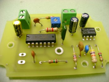
I chose to mount the tuning potentiometer directly to the PCB and just drilled a hole in the enclosure to access it with a screw driver. If you have access to panel-mount recessed pots, I would probably go with those, but they can be a bit spendy, and can be hard to find. Space is a little tight in this box, so make sure you get the square rather than the long rectangular package.
Check out the eagle files and gerbers on github. There are also some LTSpice simulations I used while designing the hardware.
Next Steps
Currently 5 of these sensors are mounted in a fabric sleeve on my upright bass. Unfortunately the cabling for power and the 0-5V output makes the system rather bulky. I would like to redesign these to be wireless and battery-powered, sending their data to a USB stick instead of analog output that is collected by a separate ADC. It is also currently rather difficult to calibrate the sensors using the internal potentiometer. By using a microcontroller onboard I should be able to implement an automatic calibration.