This is the first in a series of tutorials intended to introduce LTSpice to the uninitiated. LTSpice has some rather unusual interface conventions that take some getting used to, but it’s an incredibly powerful tool that’s available for free!
The first step is to download it from Linear Technology’s website.
Unfortunately it’s a windows-only application, but the main developer, Mike Engelhardt has gone out of his way to make it work well under WINE, so Linux users aren’t left out of the fun.
In these tutorials I’m going to spend more time talking about using LTspice specifically rather than about the electronics themselves, so I will sometimes assume a certain level of circuit design knowledge.
Adding Components
When you first start LTspice you’re presented with an empty workspace. The first thing to do is pretty CTRL+n to open up a new schematic. Then we can start placing parts.
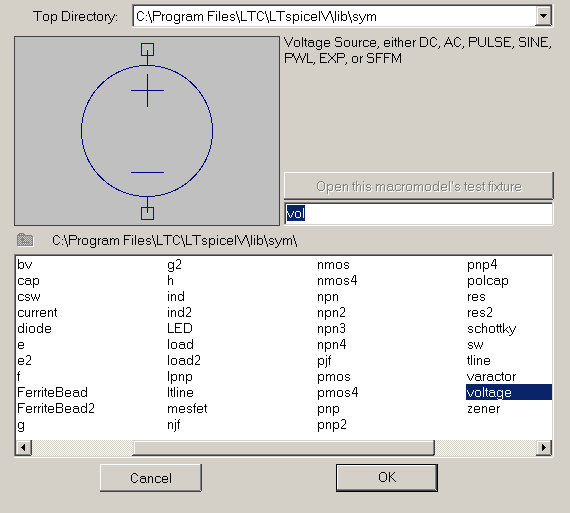
We’ll start our circuit with a simple ideal voltage source. F2 brings up a library of components divided into folders, we’ll leave most of them for later. The ideal voltage source we’re interested in is located in the default folder, so you can either scroll over to it or begin typing “voltage” into the text field and it will be selected. Press ENTER or double-click on “voltage” and you’ll see the window disappear and your cursor change to the voltage source icon. Click once on the left side of the screen to place a voltage source, then either right-click or press Escape to go back to selection mode.
You don’t have to go to the library for all components. Pressing r, l, c, d, or g will change your cursor into a resistor, inductor, capacitor, diode, or ground icon, respectively. You can rotate the cursor by pressing CTRL+r, and place the components with your trusty left mouse button. As before, right clicking or pressing Escape will get you back to the default mode.
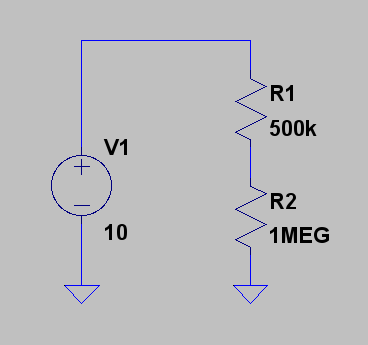
Press ‘r’ and place two resistors one over the other, as in the schematic above. Press Escape or right-click to finish.
Now press “g” and place two ground points as above. As in most schematic capture software, all the ground connections are considered to be wired to each other, and always provide a ground reference that reads 0V. Any voltages measured in the circuit are relative to this ground. You also always need at least one grounded node in your circuit.
Moving and Deleting
Occasionally you will make a mistake, and want to delete a part or move it from where you originally placed it. LTspice follows the UI convention that first you specify an action, and then you select the parts you want to act on. To delete parts simply press your Delete key, then click on the items you want gone. You can also box-select around a group of items to be deleted.
To move items, press F8, or click the closed fist icon, then click on the item you want to move, and you can place it anew. You can also press F7 or selected the open hand icon, which will also move components. The difference is that the closed-fist version will also drag along any connected wires, while the open-hand will leave them be.
Wiring it up
Press F3 to change your cursor to crosshairs, and you’re ready to wire. Simply click where you want the wire to start, then click again where you want it to end. You can click at any point on the canvas to put add intermediary points. Holding down ‘ctrl’ lets you put diagonal wires while still snapping the endpoints to the grid.
Go ahead and place the wires as in the above picture.
Changing Part Properties
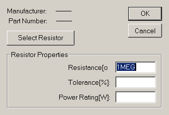
Once the components are placed, right-click on the component icon to change its parameters. You can use SI prefixes like k(kilo), m(milli), and u(micro), but you have to use MEG for mega.
Set the resistance of the two resistors to 500k and 1MEG (ohms), and the voltage source to 10 (Volts).
Simulation
Now we actually get to see what SPICE is all about: Simulation.
Click on the little running man icon on top to bring up the simulation menu. For DC circuits you’ll want to click on the “DC op pnt” tab and click OK. This will find out the steady state of your circuit. The first thing you’ll see is a text list of the voltages at all the nodes and the currents through each component. It’s not immediately obvious which node is which, so if you close the text window you can just let your mouse hover over a node or component and see the pertinent info on the status bar at the bottom.
A note about currents: Watch your signs! When you hover your mouse over a component, the current is taken to be positive if it is running down or right, and negative if it is running up or left.
Next Time
Hopefully this basic example has introduced you to the most basic elements of LTspice. As we continue I’ll introduce more sophisticated simulation types, parametric sweeps, and more!